Hello Vital MTB Visitor,
We’re conducting a survey and would appreciate your input. Your answers will help Vital and the MTB industry better understand what riders like you want. Survey results will be used to recognize top brands. Make your voice heard!
Five lucky people will be selected at random to win a Vital MTB t-shirt.
Thanks in advance,
The Vital MTB Crew

Appreciate the points you've made. I canceled my order and it was refunded by the sensor company. You're right, it doesn't make any sense with a single sensor. I just need to order the Raspberry Pi and start down that road.
Interesting post on IG from @Downamics . It’s a great visual diagram of how each part on the bike set up affects the other. It can also remind us how in the weeds we can get by making a change.
“This diagram is an overview of the scope for using DAQ as a holistic and specific analysis tool. It is not a comprehensive guide to the vehicle system or DAQ methodology.“
You can view and use the diagram here:
Downamics Framework
Anyone had any experiences with BYB using MacBook or Windows? Loading times etc
Yes, I have used BYB, with pretty fast loading times. What other info are you interested in?
So I sacrificed a string pot on the altar of science. TL;DR: So far, the results are encouraging.
I used a lathe to drive the pot via an offset crankpin, allowing me to calculate the theoretical string trajectory exactly, and the maximum velocities and accelerations at different lathe speeds. The downside of this arrangement is secondary vibration: because the string oscillates vertically, its inertia introduces an error that gets larger as the speed of rotation grows. The good news is that, because it isn’t something the pot will experience in real use and occurs at mid-stroke, I think it can be ignored: the ends of the stroke, where the accelerations are the highest, are where we expect any problems of the string overrunning the spool to occur.
RPM Peak velocity (m/s) Peak acceleration (m/s²)
530 3.78 247.6
750 5.35 495.8
1060 7.57 990.4
1500 10.71 1983.4
For reference, most of my ride files have max transient accelerations in the 200-300 m/s² range. I'm sure harder-hitting riders see higher accelerations but I think 1000 m/s² is a decent upper bound for design. That's 100g, folks.
The pot ran without any mechanical issues at the first three speeds. At 1500 RPM it failed after about 5 seconds (so even then, it got more than 100 cycles in). The mode of failure appears to have been loss of tracking of the string on the spool, possibly contributed to by wear in the grooves. I had a connecting piece of 40lb fishing line in the string which broke as intended. The string also chewed itself a new exit channel due to a minor alignment issue. In other respects the unit appears to have survived intact.
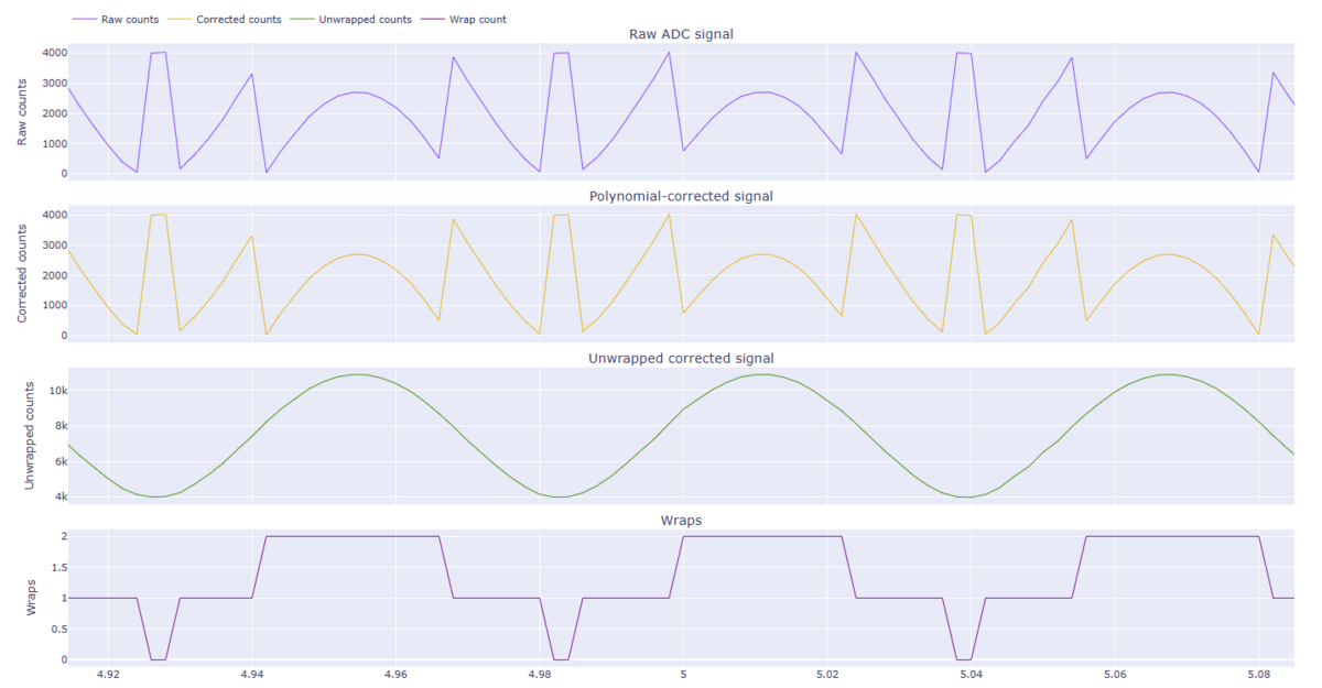
At 1000rpm the pot is tracking ideal movement pretty well - although not perfectly. The secondary vibration effects are visible in the mid stroke, along with the occasional minor bobble - cause unknown.
At 1500rpm I didn't manage to get the logger turned on before the string pot failed. But from what the string was doing, I would expect it to be ugly.
My conclusion is that this design comes pretty close to meeting the mechanical requirements. It tracks well - but not perfectly - under some very demanding test conditions - I'd expect the results to be perfectly acceptable for a fork in normal use, and better for a shock (where displacement, speed and acceleration are reduced by 2-3x). Having said that, there is scope for further reduction of both physical size and the inertia of the moving components. I have a revised version that I'll be testing shortly.
Durability is unproven at this point. The main issue I'm looking at is friction of the string at the exit point and resultant wear. I'm looking at fishing rod hardware to address this. Other longer-term issues will probably emerge.
Integration is another issue. Ideally the pot would work as a plug-in replacement for a traditional resistive linear pot. The AS5600 encoder I use does indeed have an analog output option, and can be used that way if the analog supply rail runs at a voltage that works for the AS5600, and if the logger's analog input doesn't load the AS5600 excessively. The AS5600 can also be read via a digital data bus, if your logger has one.
Because the pot is multi-turn, there is also the need to 'unwrap' the raw encoder results. Unless the analysis software happens to deal with that already (or the logger does it onboard), the results are going to look very strange. The requirement to unwrap also puts a theoretical lower limit on the sampling rate that can be used.
Various misfortunes have prevented me getting a successful side-by-side comparison to a linear pot, but that will be along soon.
There was a product called SussMyBike Flow that did something similar to this. The issue was the app sucked and eventually fell out of support, but it gave you some data ranges to work with using a similar mechanism IIRC. I have one laying around here somewhere...
You could try supporting the string near the lathe in both vertical directions to prevent these oscilations.
Yep, I'll try that for sure. There is a trade-off: as the support point gets closer, the magnitude of the secondary vibration gets larger (like short conrods in a car engine), but reduced oscillating mass ought to help. The main thing I will do is use lighter string. I have some high-tech fishing line that is 20% the weight of the stuff I'm using now so I expect that to help a lot.
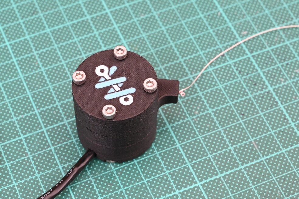
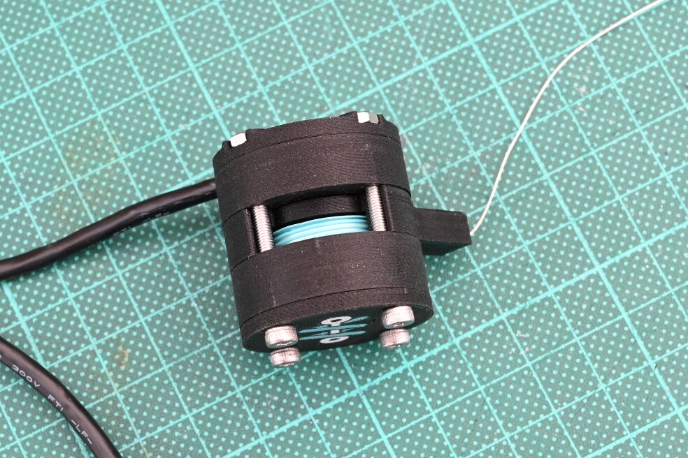
few pics of the new string pot design. It ate up 1000rpm in testing and even ran at 1500 briefly. Unlike the last time however, this time the failure was friction at the string support (thanks @Primoz, worked great) causing the connecting string to break. The pot itself survived intact and tracked the theoretical path well until the failure.
That's it for bench testing. We'll see how it performs in the wild.


I was thinking about using two bearings for support to prevent friction over the in going edge. Or at least a very rounded hole entrance.
Yeah, my solution (hole in a piece of delrin) was pretty basic, it could definitely be better.
Wondering how people interpret the 95th valve and whether it’s one of the main valves you analyse.
My $0.02: its a more consistent measurement of suspension use than the maximum, which is prone to distortion by one big event.
From what Enrico at byb told me is averages are mostly LSC and 95th/Max HSC but depending on what numbers you see it can pull your averages up. I could be wrong but this is how I interpreted what he said. Also agree with ben c on 95th being less of an outlier.
My "old" style BYB front linear pot got a bit noisy over the winter -- has any of you successfully opened and cleaned / revived such a thing?
I haven't opened my byb pots but they can usually be pryed open and you will find wipers on the end of the shaft, which contact the resistive surface on the outer tube. Clean these up with contact cleaner, and you might want to gently bend the wipers out slightly so they make better contact too.
To get it apart, there might be a grub screw to remove first. My aim ones where pressed together which needed careful gripping to pull apart. Ill have a look at my BYB ones tomorrow though, pretty sure they need it too
These are old photos but hopefully you can figure out whats going on inside them! They are all constructed in a similar way
Depending on how your suspension valving works, most of the time LSC largely affects HSC as it sort of acts as a "threshold" at which speed oil is forced through the high speed circuit. For example when running very little low speed damping most of the oil will (can freely) flow fast enough through the LSC orifice, no matter how fast the shaft speeds might be (you'll see very fast hs speeds when measuring). As soon as the low speed needle is closed off enough, oil has to flow through the high speed stack, as the orifice simply can't pass enough fluid fast enough.
I went down the rabbit hole once of trying to get high speed events down by shimming the high speed stack stiffer and stiffer, without any significant changes is the measured values – all while running very little low speed compression. Only to realise all that would have been needed are a couple of clicks low speed compression.
Of course that also works the other way around -- if your high speed stack is super soft, you can run as much lsc as you want, the oil will be able to freely pass through the hsc stack even at slower shaft speeds.
I like using 95th, I find it's a great, quick number to look at to balance the shaft speeds. I think you can get used to any number, i just started with that so know its an easy one to compare with the years of data I have.
I love the DIWhy vibes from the last few pages 😍
I have been working a lot on the App and the Firmware for the mast month or so. I have made a lot of progress into packaging it into end to end usable, both on desktop and mobile.
Major changes
You can also record live sessions.
The spring rate/damping/balance are recalculated every 1.5 seconds, while the graphs are real time. It works with two sensors and two IMUs at 1000Hz, but can be taxing on the phone.
When you hit save, it is stored locally as a session, same as the ones imported from the DAQ.
The bike editor can have a:
Minor quality of life improvements:
Mobile changes
Confirmed to be working on Android. I have not tried it myself, so I do not have setup instructions, but another dude tried it.
Working on iPhone. Right now it is somewhat tricky - you have to have a (free) Apple Developer program and do minor setup in Xcode and change the identifier.
If the project takes off I might consider setting up paid dev programs and upload it to Google Play/Apple App Store. They are $99/year so this will rely on some sort of donations.
Firmware changes:
As things finally start to settle down code-wise I will start publishing ready to use app and firmware builds. For Android it should be straightforward to have an APK for side loading, for iOS will have to see what to do without a paid program - Apple has been loosening the rules recently.
My goal over the past few months was mainly to package everything that @sghctoma has created into a usable complete package. Massive hats off to him - the travel statistics and suspension kinematics he has done are incredible.
Most of the featured I had in mind - wifi access point on the go with daq management over wifi and better parity between mobile & desktop are complete.
There are some bugs and UI inconsistencies that I will be resolving as I get annoyed enough by them or enough people complain.
Now that things are more stable I will be riding more and see what else can be done to the kinematics stuff and calculations.
If you try this out and notice something is off or can be improved, please, please, please, write an issue in the App repo or the Firmware repo
My setup is linkage driven with bearings and cheap rotational sensors ($3 each)
The kinematics setup in the app then translates the angle of rotation of the sensor into shock/wheel travel.
The firmware/app also support linear sensors.
I have compiled extensive documentation on both the firmware architecture, hardware build and daq operation.
There is another architecture document for the app which explains the telemetry and kinematics calculations.
Looking real slick! I'm off for a hunt around in your repo 😉
Damn that is looking cool! well done on all the impressive work here - I've followed that project since the early days and love to see how far its come!
I opened up my BYB fork sensor to clean it up - was a little easier than the AIM ones were - its a snug fit but not as tight since the screws hold it in place, so can be carefully pryed apart with a metal spudger or blade. The wipers looked pretty good, a tiny bit of dirt in there so I'll clean it out, replace the o-rings and add a tiny amount of thin super lube grease to the contact points to reduce friction and give smoother contact for the wipers. It had quite a lot of play in the shaft too so I would like to tighten that up a tiny bit if possible to reduce rattle. In the past I lathed a new sealhead with a tighter fit in smaller pots, and these look like a standard linear bearing but I haven't found one online yet
- The project has a build website: www.bodaqs.net has sourcing and build guides for the hardware, a user guide for the logger, and a software guide, as well as an overview of the project.
- syn.bike compatibility. The logger can output files for direct upload to data.syn.bike, which is a simple, clean option that will satisfy most users. I'm still working on my own software, but that is going to take time and I don't want to reinvent the wheel (more than I have already).
- Another iteration of the hardware. Same basic functionality but better power management and works around an ADC issue.
If you fancy taking a look at the build website - even if you don't think you'll be building a data logger - any feedback would be appreciated. If you take a look and decide you want to give it a go, I'm looking for beta testers - hit me up.
Yes yes yes, love this so much! Finally somebody else trying to use rotational sensors for the rear. Probably due to the same "Santa Cruz Shock Tunnel Syndrome" that caused my preference for those sensors 😉
Will definitely look around in your repo and maybe try the app (I'm an Android User as well). As far as I remember, my files probably should be compatible with the sufni project.
The software looks awesome as well as the mounting idea for the sensor!
Credit goes to sghctoma who originally did the rotational sensors. I have ordered some linear sensors, but I don't think I can fit anything in the SC tunnel...
I got tired of the cave look, so now with light mode! Also - lots of quality of live improvements for the sessions.
Something that I have enjoyed a lot implementing - automatically matching a selected segment from a session against all other recorded sessions and showing a statistics comparison. Strava segments, but for telemetry! I will not be releasing this in the public repo at this point.
Go the light mode! I thought I was in the minority with everything coming in dark mode these days
That's very slick. Well done!
2 different position vs velocity charts, different riders, different tracks. Top image is a boxxer with 3.2 damper and second is with 3.1 damper. Obvious from the second image that the rebound in the rear could do with speeding up, average is -253mm/s and max at -1327mm/s.
First image average rebound is -390mm/s and max at -2697mm/s.
Post a reply to: Suspension Data Acquisition