Hello Vital MTB Visitor,
We’re conducting a survey and would appreciate your input. Your answers will help Vital and the MTB industry better understand what riders like you want. Survey results will be used to recognize top brands. Make your voice heard!
Five lucky people will be selected at random to win a Vital MTB t-shirt.
Thanks in advance,
The Vital MTB Crew


Start by finding the moment due to rider weight about the chainstay pivot on the front triangle. Since this is static, the sum of the moments about that point must be zero. This will allow you to find the reaction force at the seat stay. Remember since everything is pinned, the force can only be along the axis of that member. Similarly, you can then do a sum of moments about the upper link pivot on the front triangle to find the reaction force at the shock.
Right - so when you say everything is pinned, does that mean that point F only has a force acting vertically against the rider's weight divided by two? (i.e. no Fx and only Fy) If this is true, would this also mean that the shock is only feeling forces along its length?
The rear wheel force would be half the rider weight as described here. In the case of a member that’s pinned on both sides, the force vector is along the axis that connects the two pinned points. So the shock can only experience tension/compression. That makes the second question about the direction of the force through the shock easy. The direction is the orientation of the shock.
Ahh, I forgot about the force vector being along the axis that connects the two pinned points. That's my bad. Thanks to your help, I actually have an answer now, which is a significant improvement compared to ~an hour earlier. I didn't expect you to reply at all since I posted this thread half jokingly, but I honestly appreciate it 👍
What did you get?
While I was redoing my work to make it clearer, I realized I made a mistake while taking the moment about the chainstay pivot (literally the first step 😭)
For some reason, my forces at the rear axle / seatstay sum to zero.
Anyways, after throwing a bunch of shit at the wall, I got a variety of answers ranging from 150, 178, all the way to like 700-something. I'll probably regroup with my study group tomorrow and try to squeeze into office hours next week.
The moment about the chain stay due to weight is correct at 82.5*465. The remainder of that equation needs to be for the seat stay. So you’d see things like 175/459.62 (similar triangles like you are using but for the seat stay).
The 178 number is off by a very small amount. A fraction to be specific.
155.08
This is what you get if you only account for the y component of the reaction force at the seat stay. If the rear axle were to be horizontal from the chain stay pivot that assumption holds, but in the case of it being offset, both the x and y components of the force contribute to the moment.
would read again.
Yep. Fascinating diversion.
What school / collage grade is this?
Oddly enough, the drawing of the diagram I sent in the first image was wrong - the rear axle should be coincident with the chainstay pivot as per the answer key. The free body diagram I have at the bottom of the page shows the corrected pivot points. Due to rounding errors, my answer came out as -169 but the answer key says it should be -164 point something; fortunately, the TAs are pretty generous with rounding so I'm just gonna leave it as that.
Statics class, but honestly this is a fair question for Physics 1.
I’m not sure about this diagram. Is what’s sketched here accurate? Because if so, the answer is 155.178.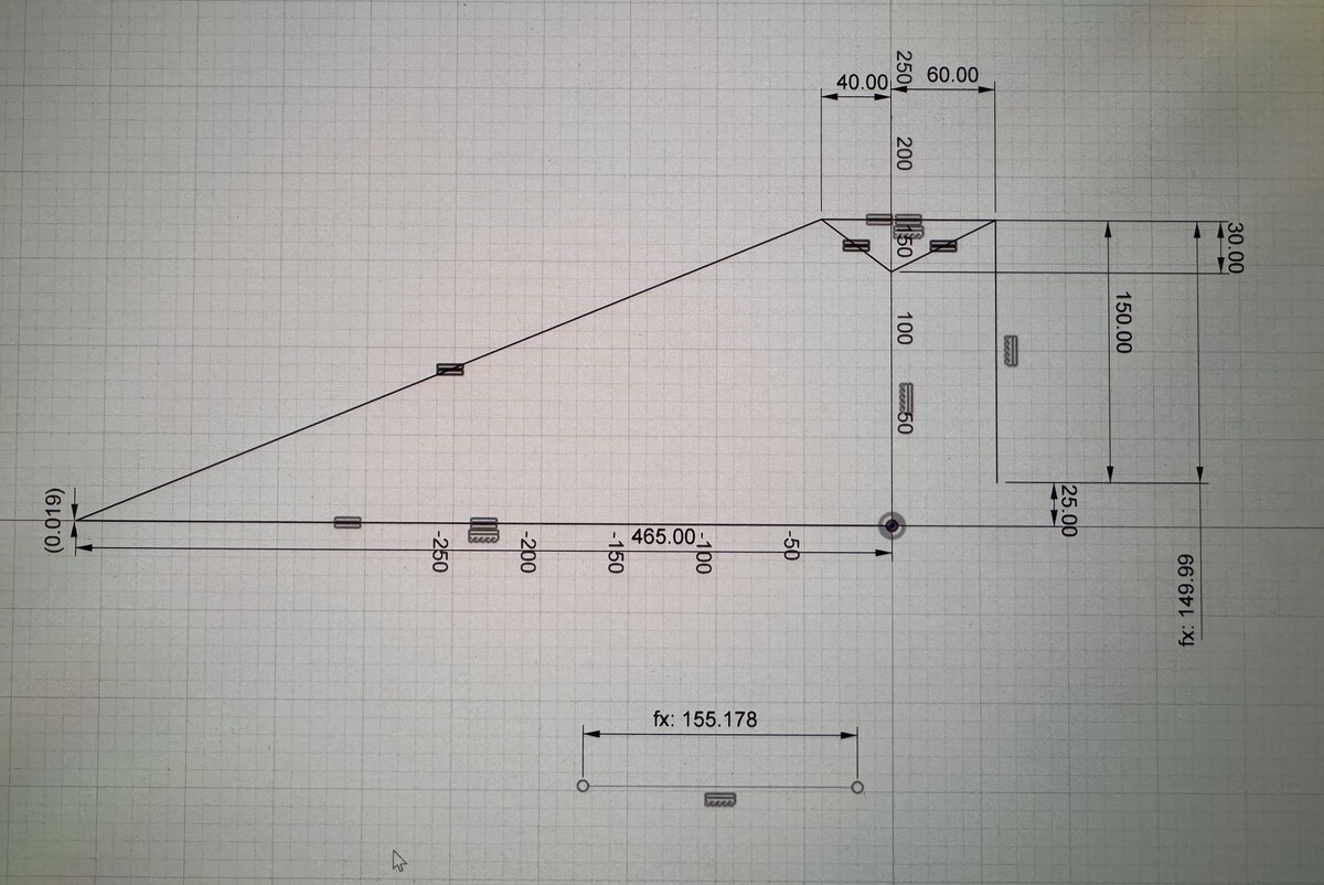
Okay, after I redid it I got the same answer. I'm just as confused as you are as to why the diagram they gave us, which positions the rear axle below the chainstay pivot, is apparently drawn incorrectly according to the answer key. The diagram you sketched is correct according to the answer key, but at this point, I think it's probably fine to double-check with the professor to see if the answer key is wrong.
The dimensions aren’t well drawn to be honest. What I did there is a graphical approximation of leverage ratio by the way. If you dimension the shock ever so slightly shorter (in this case 0.01 mm) and then look at the vertical displacement of the rear axle and divide that number by the difference in shock length it gives you appropriate leverage ratio. As the difference in shock length approaches zero, the approximate leverage ratio approaches the actual leverage ratio.
Yeah, I agree that the drawing isn't great. Unfortunately, I don't have access to the answer key so I can't just reference it to see the work that we are actually expected to do; things will probably be clearer once I talk to the professor about it.
It's cool to see the way that leverage ratio is calculated. I'll definitely try to learn more about it in my own time
y.chainstay pivot = y.split pivot -----> 155.08
y.chainstay pivot = y.split pivot - 25 -----> 178.51
(ritter section applied)
I checked with the professor today and it turns out the answer key accidentally used 425 instead of 465, which was what gave the incorrect answers.
Due to the unclear diagram, any answer close to 155 and 178 should be accepted. 👍
Thanks for the help! Out of curiosity, how did you solve for the force through the shock in Solidworks?
It's just an equation driven dimension on a line. The equation is (d/(l1-l2))*F where l1 is the initial shock length, l2 is a second shock length, d is vertical wheel displacement, and F is the axle load. This equation is an approximation of the actual leverage ratio. The smaller the difference between l1 and l2, the closer the approximation is to the actual leverage ratio. A difference of 0.01 mm is plenty small to get a very accurate number. The quick and dirty is make l2 1 mm less than l1 and then you wheel displacement is approximate leverage ratio, however it's a little less accurate than using a smaller step.
Post a reply to: @Cascade Components - Homework Help